03 - Volumetric Ray Marcher
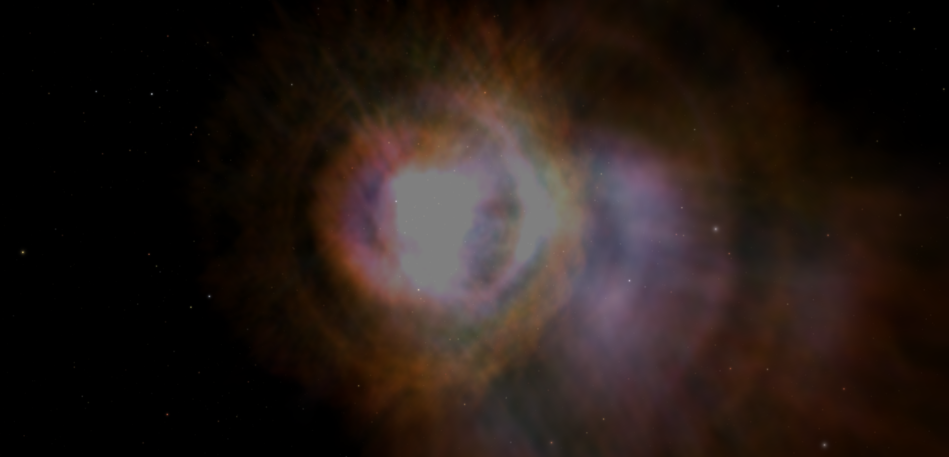
In this article, we are going to talk about an implementation volumetric ray marching. The module VolumetricExample.zip includes a volumetric .dds file of NGC6302, which is pictured below. In this technique we treat each fragment as a line of sight. We step through a volumetric data set along these lines of sight, and integrate the colors sampled at each step along the line of sight. This module can be quickly changed between using the colors in .dds file directly, as is the case in the picture below, and applying a color map, or transfer function, to the data stored in the .dds file. This article builds on shader and mesh configuration concepts discussed in Adding Surface Markers. Here we are going to focus on loading textures in the mesh configuration file, macros, and the fragment shader implementation of a simple ray marcher.

VolumetricExampleMesh.usesconf

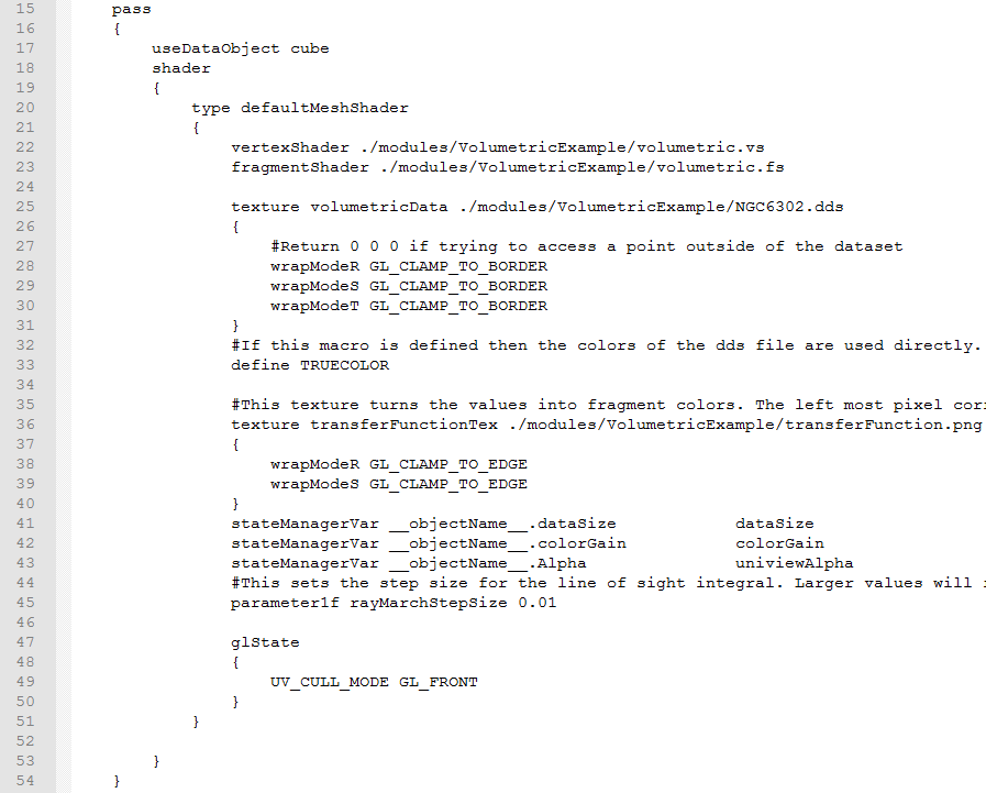
This is a screenshot of a section of the mesh configuration in this module. In particular this is the single pass in the mesh configuration file with some of the comment lines truncated. We are using a cube mesh, which represents the cubic region of space that the volumetric dataset will occupy. On lines 25 through 31 we load the volumetric texture. We start by saying that we want to load in a texture using the keyword "texture". We then give the texture a name, in this case "volumetricTexture". This is the name that we will use to access the texture in the fragment shader. Next we specify the path of the texture file that we want to load. Finally, we can specify settings for the texture between "{" and "}".
Here we are modifying the wrap mode of all three dimensions of the texture with "wrapModeR", "wrapModeS", and "wrapModeT". OpenGL texture coordinates are in the range 0 to 1. The wrap mode specifies what happens when the shader tries to access texture coordinates outside of that range. The default mode is "GL_REPEAT". This repeats the texture, which means that the texture coordinates -0.9, 0.1, and 1.1 are equivalent when using this wrap mode. For the volumetric texture, we do not want to be able to sample values from texture coordinates that are outside of the 0 to 1 range. That is why we change the wrap mode to "GL_CLAMP_TO_BORDER" which returns a border color. By default the border color has all four channels set to 0, which is perfect in this case, as that means that samples outside of the 0 to 1 range will return a value that does not contribute to the line of sight integral.
We also load the transfer function as a texture on lines 36 through 40. This allows editing of the transfer function without changing the fragment shader. Using a texture also allows arbitrarily complicated color maps with out the performance overhead of a lot of conditionals. Since this function represents a color map, we want to set the texture wrap mode so that values less than 0 sample the texture as though they were 0, and values greater than 1 as though they were 1. This is what the wrap mode "GL_CAMP_TO_EDGE" does, and so we use this as the wrap mode of our transfer function texture.
We also define a macro in this mesh configuration file on line 33. Macros allow us to compile or not compile sections of shader coder depending on if the macro is defined or undefined. This allows us to change the behavior of the shader without the overhead of a conditional. However, you have to reload both the module and the shader before these changes take effect. This makes macros a good choice for properties that you do not need to change at runtime. In this case our macro is called "TRUECOLOR". If it is defined, it indicates that the volumetric .dds file is a true color file, and we can sample colors directly from the .dds file. If "TRUECOLOR" is not defined, which you can do by deleting this line or commenting it out by prefacing it with a "#", the .dds file stores data, and we apply the transfer function to the data in the .dds file. Finally, we pass the built in alpha property to the shader on line 43 and pass another property called "rayMarchStepSize" on line 45 that is not bound to the state manager using the "property1f" keyword.
volumetric.fs

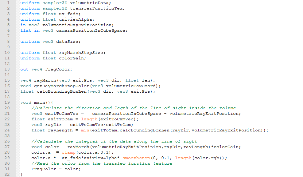
We start the fragment shader by declaring the uniforms, inputs, and outputs. In particular, we define the uniforms that correspond to our volumetric and color map textures on lines 1 and 2. The volumetric texture is a three dimensional texture, and so the data must be of type "sampler3D". Since the color map texture is two dimensional, it is of type "sampler2D". We also get the camera's position and the ray's exit position from the vertex shader. This section also includes declarations of functions, on lines 15 through 17, which we define later. The declaration specifies the functions return type, name, and arguments, where as the definition specifies all of the aforementioned and the code to execute when the function is called. We declare the functions here, because we call them in the main function, and non main functions must be declared or defined before they are called. The first function takes an exit position, a direction an a length, performs the ray marching and line of sight integration and returns the result of that integration. The next function takes volumetric texture coordinates and returns the corresponding color. The final function takes a ray's direction and exit position, and calculates the distance between the entrance and exit positions.
For the main function, we start by calculating the direction of the line of sight and the distance between the exit position and the camera on lines 21 through 23. On line 24 we calculate the ray's length by taking the lesser of the distance between the camera and the exit position and the entrance and exit positions. We calculate the distance between the entrance and exit positions using the "calcBoundingBoxLen" function we declared earlier. On line 27 we use the ray march function to get the result of the ray marching operation and multiply that by a gain factor. On line 28, we use the "clamp" function to make sure that the alpha value is in the 0 to 1 range. If the old alpha value was less than 0 or more than 1, then the new alpha value will be 0 or 1 respectively. Otherwise the alpha value is unchanged. On line 29 we fade out the alpha value based on the enable/disable fading value, the object's "Alpha" value and if the fragment is black or not. Finally we output the resulting color.

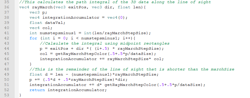
This is the definition of the ray marching function. We start this function on lines 37 through 40 by declaring variables that we will set in the marching loop. Since most of these are set in each iteration of the loop before they are used in that iteration, we do not initialize them here. The exception is the "integrationAccumulation". At the end of each loop we add that step's contribution to the line of sight integral to "integrationAccumulation". We initialize this to a vector of all 0's so that "integrationAccumulation" is the result of our line of sight integral once we have finished the ray marching. On line 41 we calculate the number of iterations of our loop. We divide the length of the ray by the step size that was set in the mesh configuration file to get the number of steps, which is the ceiling of the result. The last step of the march is likely to be shorter than the others, so we want to deal with it separately. This means that the number of loop iterations should be the number of steps minus 1. This means that the number of loop iterations is the floor of the ray length divided by step size. Fortunately, when you cast a float to an int in OpenGL, the resulting int is the floor of the original float. That means we can just use the "int()" function on the quotient to get the number of loop iterations, since we need to cast the number of loop iterations to an integer anyways.
Lines 42 through 47 make up the ray marching loop. On line 42 we specify the properties of the loop by declaring a loop counter "i", keep looping while "i" is less than the number of loop iterations and incrementing "i" at the end of each loop iterations. On line 43, we calculate the midpoint of the current step, using the ray exit position, ray direction, loop counter and step size. We start from the exit position of the ray and goes toward the camera. This provides much better stability when zooming in and out compared to going away from the camera. We then transform the midpoint of the ray from between -"dataSize" and +"dataSize" to between 0 and 1 and look up the color at those texture coordinates using the "getRayMarchStepColor" function. Finally we add the contribution of this step's color to "integrationAccumulator". We add the contribution of the final step on lines 48 through 51. Since this step is most likely shorter than the step size, we first have to calculate the size of this last step. Once we added the final step's contribution, we return the result of the integration, which is stored in "integrationAccumulator"..

Here we define the function "calcBoundingBoxLen" that given a ray's direction and exit position will return the distance between the ray's entrance and exit positions. We iterate over the x, y and z directions. For each direction, we calculate the distance along the ray from the exit position, towards the camera, to the appropriate bounding plane normal to that direction. That calculation is done on line 65. However, this calculation involves dividing by the appropriate component of the ray direction. Before we do that, we need to make sure that the component of the direction is far enough away from 0 to avoid division by zero. That is done on lines 60 through 62. Finally, we return the smallest of the three component. This corresponds to the first time the ray crosses a bounding plane, and so it is the distance where the ray exits the box.

This is where we sample either one or both textures to get the color values for each ray march step. The exact behavior depends on whether "TRUECOLOR" is defined or not. If "TRUECOLOR" is not defined in the mesh configuration file (i.e. if the line "define TRUECOLOR" is deleted or commented out), then the "#ifndef" branch on lines 75 and 76 will be compiled and executed. If "define TRUECOLOR" is included in the mesh configuration file, then the "#ifdef" branch on line 79 will be compiled and executed. Either way we have to sample the volumetric texture at the desired coordinates. We do that with the code "texture(volumetricData, volumetricTexCoord)". The "texture" function takes a texture sampler as its first argument and the texture coordinates to sample as its second argument. If "TRUECOLOR" is defined, then we just output the resultant color. If "TRUECOLOR" is not defined, then we use swizzling to extract the first component of the .dds file data. Vectors can be swizzled on "r", "g", "b", and "a", just like they can be swizzled on "x", "y", "z" and "w". We then use the data we read from the .dds file to look up the color in the transfer function texture. This is done in mush the same way as sampling a three dimensional texture, except using a two dimensional vector for the texture coordinates instead of a three dimensional vector. Finally we return the result of the transfer function texture lookup.
Служба підтримки клієнтів працює на UserEcho

