02 - Earthquakes, .raw Files, and Geometry Shaders
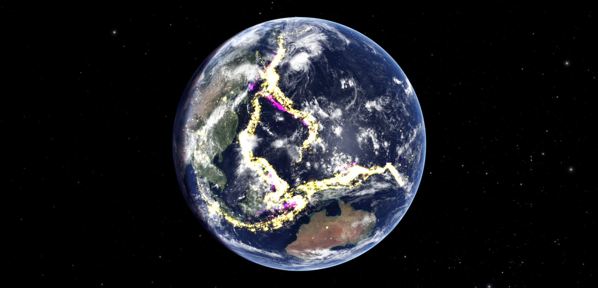
In this article we are going to talk about .raw files and geometry shaders, using the earthquake module that is built in to Uniview as a case study. You can see a screenshot of the Earthquake module below. This article builds off of the mesh configuration, vertex shader and fragment shader techniques discussed in Adding Surface Markers.

ge1quakes.raw

Pictured above are the first 20 lines of ge1quakes.raw. This image serves as a good example of a .raw file. A .raw file contains nine floats per line. While these nine floats could represent anything, typically the first three values are the x, y and z components of the point's location. The other six floats usually contain auxiliary data about the point. In this case the fourth float value is the magnitude of the earthquake, and the fifth float is the normalized time when the quake occurred. Uniview reads each line as the three corners of a triangle. This means that the vertex shader only has access to three of the floats on the line at a time, but the geometry shader has access to all nine floats.
There are a few tricks involved in using .raw files that should be mentioned here. The first is that we disable optimization of the .raw file mesh in the mesh configuration file with "dataHints dataMesh1 disablePostprocessing" where "dataMesh1" is the name that we gave the .raw file in the configuration file. This speeds up loading and prevents the culling of degenerate triangles. Since we are using the triangles as a way to load data into the geometry shader, we want to disable the culling of degenerate and preserve all of the lines in the .raw file. We also keep the vertex shader simple in this case, as its purpose is to pass the data from the .raw file to the geometry shader. When using a .raw file, the vertex shader just executes the line "gl_Position = vec4(uv_vertexAttrib,1.0);" to pass the data in the .raw file to the geometry shader inside the first three components of "gl_Position".
meshpass0.gs

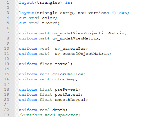
The above is a screenshot of the first portion of the geometry shader in the earthquakes module. The geometry shader is executed once per geometric primitive. It takes a geometric primitive as input and can output some number of geometric primitives of the same or different type. Like in the vertex and fragment shaders discussed in Adding Surface Markers, this first portion of the shader is where we declare the inputs, outputs and uniforms for the geometry shader. There are a few differences, however. This is a geometry shader, so the inputs and outputs of the shader are geometric primitives. The types of primitives that the geometry shader can use for inputs of outputs are listed here: https://www.khronos.org/opengl/wiki/Layout_Qualifier_(GLSL)#Geometry_shader_primitives.
On line 1 we declare the type of the geometric primitive that serves as the input to the geometry shader. We are using a .raw file as our input model, and the way that .raw files work is that the each line in the .raw file is treated as a triangle. Thus our input geometry primitive type is “triangles”. On line 3, we declare the type of any geometric primitives that will be output. In this case, the goal of the geometry shader is to create a single quad for each line of the .raw file. There is no quad primitive that we can output, so what we do is that we output a triangular strip with four vertices. This draws two triangles, one with the first, second and third vertices, and one with the second, third and fourth vertices. Putting these two triangles together, we can create a quad. You can read more about triangle strips here: https://en.wikipedia.org/wiki/Triangle_strip. We also need to tell the geometry shader the maximum number of vertices that it can emit across all output primitives. We do this by setting the "max_verticies". Since we only want to emit one primitive with 4 vertices, we set "max_verticies" to be 4. If we wanted the option to emit up to three quads in a single execution of the geometry shader, we would need to set “max_vertices” to 12, even though no single primitive contains more than 4 vertices. On lines 4 and 5 we specify the per-vertex outputs, just like we do in a vertex shader. Finally we declare all the uniforms that we will use in the geometry shader.

Above
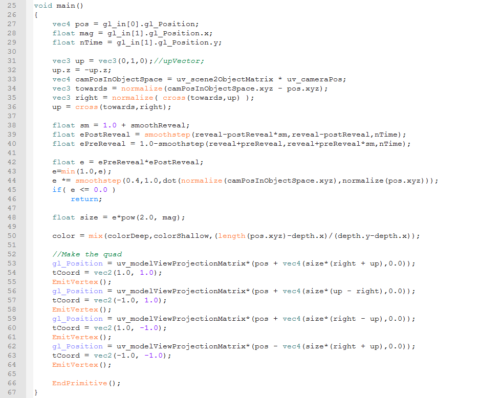
is the main function of the geometry shader. We start on lines 27
through 29 with extracting the values from the .raw file. The "gl_in" array allows us to access the vertices that make up the input
geometric primitive. We passed each third of the data in the .raw
file through the vertex shader using "gl_Position", This means
that the first, second and third columns of the .raw file are the
first three components of "gl_in[0].gl_Position", the fourth,
fifth, and sixth columns are the first three components of "gl_in[1].gl_Position", and the seventh, eighth and ninth columns
of the .raw file are in the first three components of "gl_in[2].gl_Position". Here we extract the position of the quad
from the first three columns, the magnitude of the earthquake from
the fourth, and a normalized time from the fifth.
On
lines 31 through 36 we calculate the vector from the center of the
earthquake quad to the camera, We then use normalization and cross
products to get two unit vectors, called "right" and "up", that
are perpendicular to both each other and the vector between the
quad's center and the camera. This means that by using "right" and "up" as the x and y directions of the quad we draw a quad that faces the camera. Lines 38 through 43 change the
size of the quad, using a multiplicative factor called "e",
depending on where we set the cutoff time and the reveal properties
that are set in the state manager. Line 44 decreases "e" the
further away the earthquake is from being in line with the the camera
and the center of the Earth.
On
lines 45 and 46 we check to see if "e" is 0 or negative. If that
is the case, then we do not want to bother drawing the quad. What we
do in this case is to return from the main function to immediately
terminate the execution of the main function. If "e" is positive,
we then continue execution of the main function and calculate the final size using both the "e" we calculated
and magnitude from the .raw file. On line 50 we calculate the color
that we will pass to the fragment shader based on the quad's position
and the depth coloration settings in the state manager.
On
lines 53 through 64 we actually create the quad. First we set the "gl_Position" for each vertex by offsetting the position in the
.raw file along the "right" and "up" directions by an amount that depends on the size we calculated. We
then use "uv_modelViewProjectionMatrix" like we did in the vertex
shader in
Adding Surface
Markers,
and assign the result to "gl_Position". Next we set "tCoord" to output texture coordinates of that vertex in the
quad. Finally we output the vertex with a call to "EmitVertex()".
This outputs a vertex with the position, "tCoord" and "color" attributes that were last set before we emit the vertex. Since we want every vertex in the quad
to have the same value for "color", we only need to set it once
before we start emitting the vertices. However, since we want each vertex
In the the quad to have a different position and texture coordinates,
we assign a different value to "gl_Position" and "tCoord" before every call of "EmitVertex()".Once we have finished
emitting all the vertices in a primitive, we call "EndPrimitive()" to signify we have finished emitting the vertices for a primitive. If
we want to output multiple primitives, then we call "EndPrimitve()".
If we wanted to output multiple primitives, we would call "EndPrimitve()" once for each primitive that we wanted to output.
Сервис поддержки клиентов работает на платформе UserEcho

