01 - Adding Surface Markers
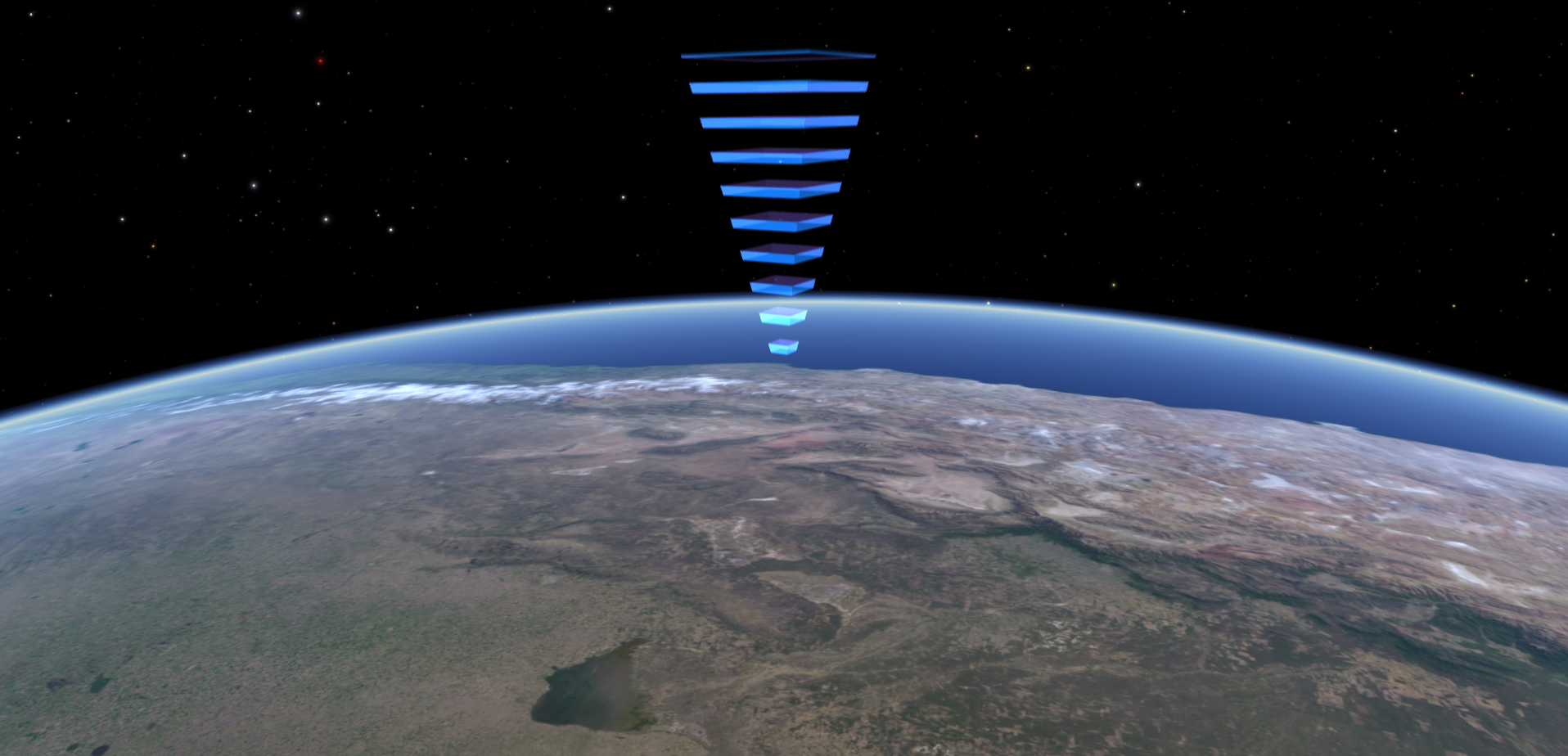
In this article we will cover adding surface markers that look like the screenshot below, and discuss some properties and techniques for vertex and fragment shaders. The module EarthSurfaceMarker.zip is based off the default Mars Lander Markers module, but has been modified to add the ability to change the module's properties at run-time. This module uses surface location positioning, which is covered in the article titled Placing a Model on the Surface of Earth.

Changing the information about the module that is shown in the profile editor can be accomplished by editing the module.definition and description.html files. The mod file is very similar to the mod file that is discussed in Placing a Model on the Surface of Earth with some minor additions that deserve a brief mention. "lsize", "lcolor", and "displayname" set the size, color, and text of the object's label in Uniview respectively, where as "off" tells Uniview that the object should be turned off when Uniview first starts up. With that out of the way, we can focus on the unique portions of this module, the mesh configuration file and the custom shaders.
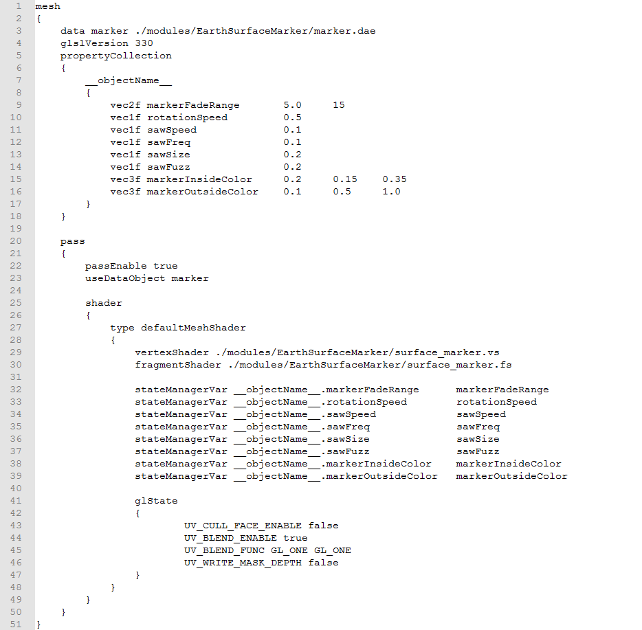
SurfaceMarker1Mesh.conf

First in the file we load in mesh for the marker on line 3. On line 4, we specify the GLSL version for the shaders we are using. This serves as the version directive for the shaders which is discussed more here: https://www.khronos.org/opengl/wiki/Core_Language_(GLSL)#Version. In this case we use version 3.3, which is a good default choice.
Lines 5 through 18 specify a property collection for the object. The property collection will appear in the state manager under the name of the property collection. This name is specified on line 7. In this case we have used the keyword "__objectName__" which will be replaced by the object's name when the configuration file is attached to an object in the mod file. In this case our object's name is "SurfaceMarker1Object", so the property collection has the name "SurfaceMarker1Object". If we were to use this configuration file for an object called "SurfaceMarker2Object" as well, then there would be two independent instances of the property collection named "SurfaceMarker1Object" and "SurfaceMarker2Object". Lines 9 through 16 specify the properties that should be added to the property collection. The first item in each line specifies the type of the item in the property collection. In this case we are using "vec1f", "vec2f" and "vec3f", which denote a single float value, a vector of two floats, and a vector of three float values respectively. You can also include a vector of four floats by declaring "vec4f", a checkbox boolean by using the keyword "bool", or a single integer by declaring "vec1i". The next item in each line is the name of the property. These will be displayed in the state manager in alphabetical order with the names that start with capital letters preceding those that start with lowercase letters. The next item or items (depending on the type of the property) are the default values for these properties.
The passEnable command on line 22 allows you to quickly enable or disable the given pass. We want to make sure that this pass is enabled. We specify the custom shaders that we are using on lines 29 and 30. Note that the vertex shader is executed first and is run on each vertex of the model, and then the optional geometry shader is executed
, and runs once on each geometric primitive, and then finally the fragment shader, which is run on each fragment, which is essentially the software's equivalent of a pixel. If you are interested, you can read more about the OpenGL pipeline here: https://www.khronos.org/opengl/wiki/Rendering_Pipeline_Overview. Lines 32 through 39 tell Uniview to pass the values from the state manager into the shaders. The "stateManagerVar" keyword says that we want to bind a value from the state manager to the shader. The next item specifies the name of the value in the state manager that we want to bind. This takes the form [collection name].[property name]. The properties in this case are all from the property collection defined above, but that does not have to be the case. Finally we tell Uniview what to call the property in the shaders. At least one of the shaders in the pass should have a uniform of this name.
Lines
41 through 47 specify different OpenGL rendering settings. Since it
is possible to see both the front and back of our marker, we disable
face culling on line 43. This means that both the front and back
facing polygons of our model are rendered. If appropriate, we could cull either the front or back facing polygons to
improve performance. Lines 44 and 45 enable blending and specifies
the blending function. In this case we want to use additive blending,
so we use the blending function that adds the source and destination
colors together. First we specify a multiplicative factor for the
source color, and then a multiplicative factor for the destination
color. A list of the different factors can be found here:
https://www.khronos.org/registry/OpenGL-Refpages/gl4/html/glBlendFunc.xhtml.
Finally we exclude writing the depth of the marker to the depth
buffer. That means that we can still render out items behind the
marker, which is what we want.
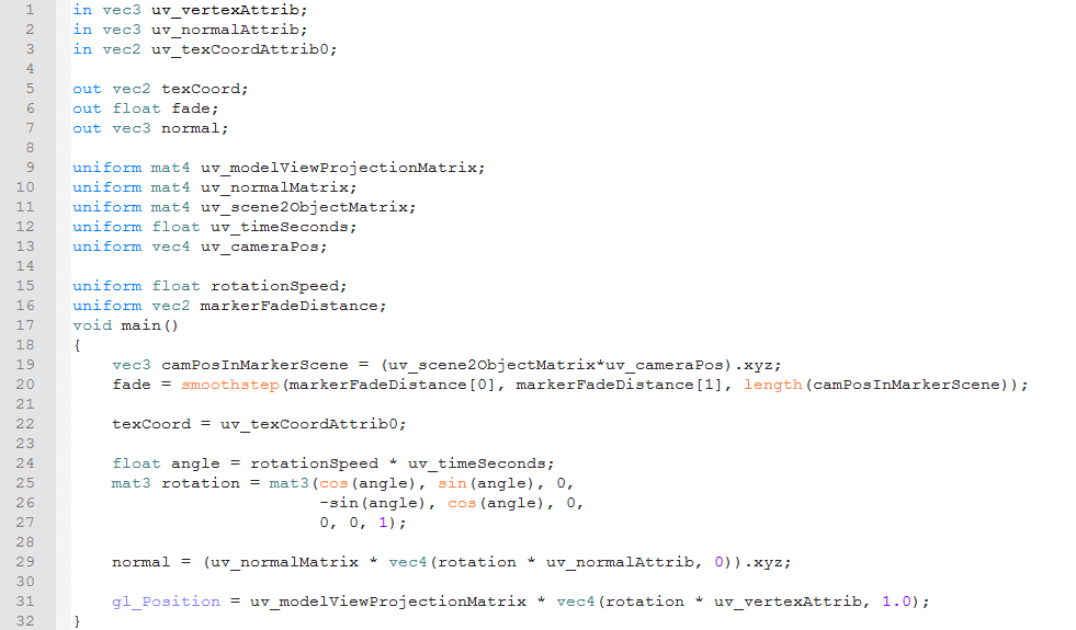
surface_marker.vs

This is the custom vertex shader for the surface marker. The first 16 lines contain different variable declarations. Variables of the type "vecn" are vectors of floats that contain n elements; where as variables of type "matm" are mxm matrices of floats. Lines 1 through 3 are where we declare the inputs to the vertex shader. These values come directly fro the model file. "uv_vertexAttrib" is the name that Uniview gives to the coordinates of the vertex in the model, "uv_normalAttrib" is the name that is given to the vertex normal in the model file, and "uv_texCoordAttrib0" is the texture coordinate of the vertex as specified in the model file. Lines 5 through 7 declare the outputs of the vertex shader to the fragment shader. These values are set in the vertex shader, and then read as inputs in the fragment shader. By default the values in the fragment shader are interpolated based on the values at the vertices that form the polygon that contains the fragment. The interpolation can be disabled by prefacing the declaration with the keyword "flat". Here we are passing the texture coordinates, a fading factor and the normals to the fragment shader. The vertex shader must also output a four element vector "gl_Position" which is the vertex's position in clip space.
The next two sections contain declarations for the shader. Uniforms are variables that may change from frame to frame, but are constant within any given frame. They are usually passed into the shader from Uniview or another application. Here the uniforms that contain the prefix "uv_" are passed to shader from Uniview automatically. These are all the declarations on lines 9 through 15. "uv_modelViewProjectionMatrix" is the product of the model, view and projection matrices. In short, this matrix is the transformation from coordinates in model space to coordinates in clip space. The "uv_normalMatrix" provides a similar transformation matrix, but in this case it transforms the normal instead of the position. "uv_scene2ObjectMatrix" is the transformation matrix from the scene that the camera is in to the model's coordinate system. "uv_timeSeconds" gets the systems time in seconds, and "uv_cameraPos" gets the position of the camera in the coordinates of whatever scene the camera is in. Lines 17 and 18 are where we declare the custom uniforms. These uniforms have the names that we set earlier in the mesh configuration file.
Lines 20 through 35 are where we include the code that is executed when we run the shader. This is wrapped in a "main" function that takes no arguments and has a void return type. We start by calculating a fading factor depending on how far the camera is from the origin of the model's scene on lines 22 and 23. We start by getting the camera's position in the model's coordinate system. We transform from the camera's position in the current scene to its position in the model's coordinate system by multiplying it by the "uv_scene2ObjectMatrix". The result of this matrix-vector multiplication is a four element vector, where the first three elements are the x y and z components of the camera's position in the model's coordinate system. Since we are only interested in the first three components of the resulting vector, we extract those using the swizzle operation ".xyz". You can read more about swizzling here: https://www.khronos.org/opengl/wiki/Data_Type_(GLSL)#Swizzling. We then assign the swizzled product vector into the variable "camPosInMarkerScene".
On
line 20, we actually calculate the fade value using the smoothstep
function. This function takes a lower edge value, a higher edge value
and an interpolation value. It returns 0 if the interpolation value
is less then the lower edge, 1 if the value is greater than the
higher edge and uses Hermite interpolation to return a smoothly
varying value between 0 and 1 if the interpolation value is between
the two edges. In this case we use the first and second elements of
the two element uniform "markerFadeDistance" as our low and high
edges, and the magnitude of "markerPosInMarkerScene" as our
interpolation value. This means that the marker starts fading
smoothly if the camera is closer than the second element of
"markerFadeDistance", and is completely faded away once the
camera is as close or closer than the first element of
"markerFadeDistance".
On
line 22 we pass the texture coordinates from the model through to the
fragment shader. Remember that the value of “texCoord” for each
fragment will be interpolated based on the values of “texCoord”
at the nearest vertices.
On lines 24 through 27 we calculate the rotation matrix for the marker. We first calculate the rotation angel by multiplying the rotation speed by the system time in seconds. Once we have the rotation angle we plug that in to the formula for 3x3 rotation matrix that rotates around the z-axis. The first, second and third rows of this matrix matrix are on lines 25, 26 and 27 respectively. Now that we have this rotation matrix, which we are appropriately calling "rotation", we can use it rotate the both the vertex's position and its normal.
On line 29 we rotate the vertex normal in the model file by multiplying them by the "rotation" matrix. We then want to transform the rotated normal into clip space, but the matrix to do that is a 4x4 matrix, so we have to add a fourth, or w, component to the rotated normal. That is what the "vec4(rotation * uv_normalAttrib, 0)" does. A non-zero w component allows the transformation matrix to apply a translation. Since we are transforming a normal vector here, which represents a direction instead of a position we add a w component of 0 so that the transformation matrix does not result in a translation. Once we expanded the rotated normal to a four element vector, we can apply the "uv_normalMatrix" and then extract the x, y and z components of the transformed normal using a swizzling operation. We perform a similar operation on the vertex coordinates, except since we are transforming a position instead of a direction we add a w component of 1 after rotation so that "uv_modelViewProjectionMatrix" can apply a translation to the rotated vertex position. Also, since "gl_Position" requires a four element vector, we do not swizzle the result of multiplication by "uv_modelViewProjectionMatrix".
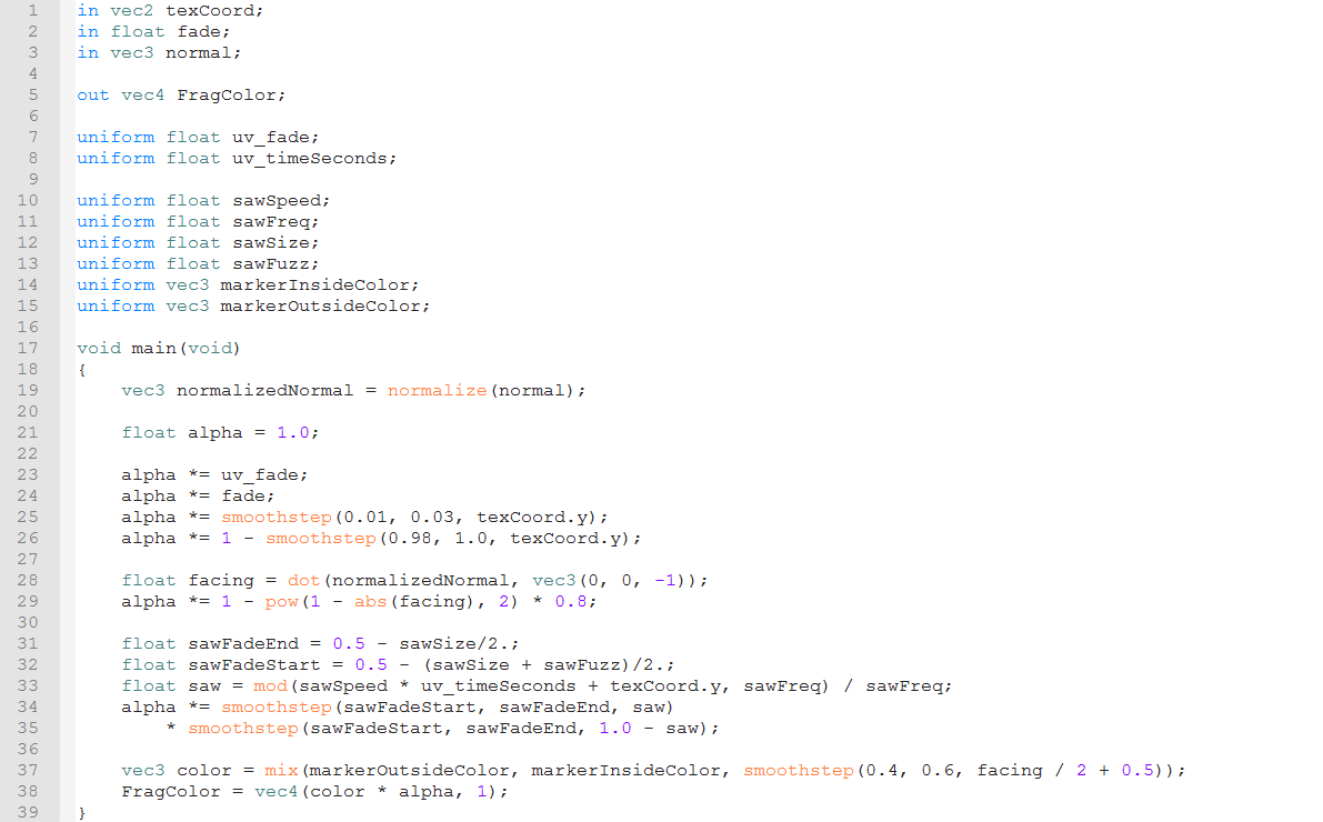
surface_marker.fs

This
is the fragment shader for our marker, and as in the vertex shader we
start with declarations of inputs, outputs and uniforms for the
shader. The inputs to the fragment shader are the same as the outputs
of the vertex shader, or the geometry shader if it is used. If
outputs of the vertex/geometry shader is declared as "flat" then
the corresponding inputs to the fragment shader must be declared as
"flat" and vice versa. We also have to declare a single vec4
output that represents the color of the fragment. The first, second,
third and fourth components of this out represent the red, green,
blue and alpha values of the fragment respectively, and all four
components should be in the range from 0 to 1. Here we have named the
output "FragColor" to clearly indicate what it represents. Also
worth mentioning is the uniform "uv_fade". This is a value that
is passed from Uniview to the shader by default, and it allows for
the nice fade in or fade out when an object is enabled or disabled in
the object tree.
Like
the vertex shader, we wrap the code to be executed in a function
called "main" which takes no arguments and has a void return
type. We first take the normal that were passed to the fragment
shader from the vertex shader and normalize them. While the normals
are normalized at the vertices, the fragment normals might not be
because the fragment normals are found by interpolating the normals
at the nearest vertices. It is unlikely that the result of this
interpolation is a unit vector, so we normalize the normals here to
be sure. On line 21, we start with a default alpha value of 1. We
then multiply the alpha value by "uv_fade" so that the marker
fades in and out as we enable/disable it. We then multiply it by the "fade" value from the vertex shader, which fades the marker out
if we get closer to it. Lines 24 and 25 use the smoothstep function
to fade out the very bottom and the very top of the marker.
On
line 28 we use the fragment normals to determine if we are looking at
the front, back or edge of of a side of a marker. A negative value
corresponds to looking at the front side of the polygon, and a
positive value corresponds to looking at the back edge of a polygon.
A "facing" value close to 0 means that we are looking at the
polygon edge on. On line 29 we fade out the fragment if "facing"
is close to 0, or if we are close to looking down the edge of that
side of the marker.
The
next block of code creates the stripe effect on the marker. Lines 31
and 32 set the size of the stripe depending on the the size and fuzz
parameters that are set in the state manager. On line 33 we create a
saw coordinate for the striping effect. We do this by taking the
height of the fragment, which is stored in the y component of
"texCoord", and offset that by the product of the saw speed and
system time to get the animation of the stripes traveling to the
surface. We then take this offset height and get the result modulo
the saw frequency, and finally normalize the result of that. This
means that "saw" changes linearly from 0 to 1 over a the
saws frequency, and then it resets to 0. Lines 34 and 35 fade the
fragment depending on "saw", "sawSize", and "sawFuzz" to
create the bands with the appropriate thickness and fall off.
On
line 37 we actually calculate the red, green and blue components of
the marker color. We do that by
mixing
together the outside and inside colors of the marker. The mix
function takes three arguments, where the first two are the values to
mix and the third value is a mixing weight. The closer the weight is
to the value of 0, the closer the mix is to the first argument, and
the closer the weight is to 1, the closer the mix is to the second
argument. Here we use mix on the "facing" value to set the
fragment's red, green, and blue to the outer color, the inner color,
or some combination of both. Finally we set the output value
"FragColor". Because we are using additive blending, which we
specified in the mesh configuration file, we multiply the color by
the alpha to get the alpha to behave as expected.
Service d'assistance aux clients par UserEcho

