Placing a Model on the Surface of Earth
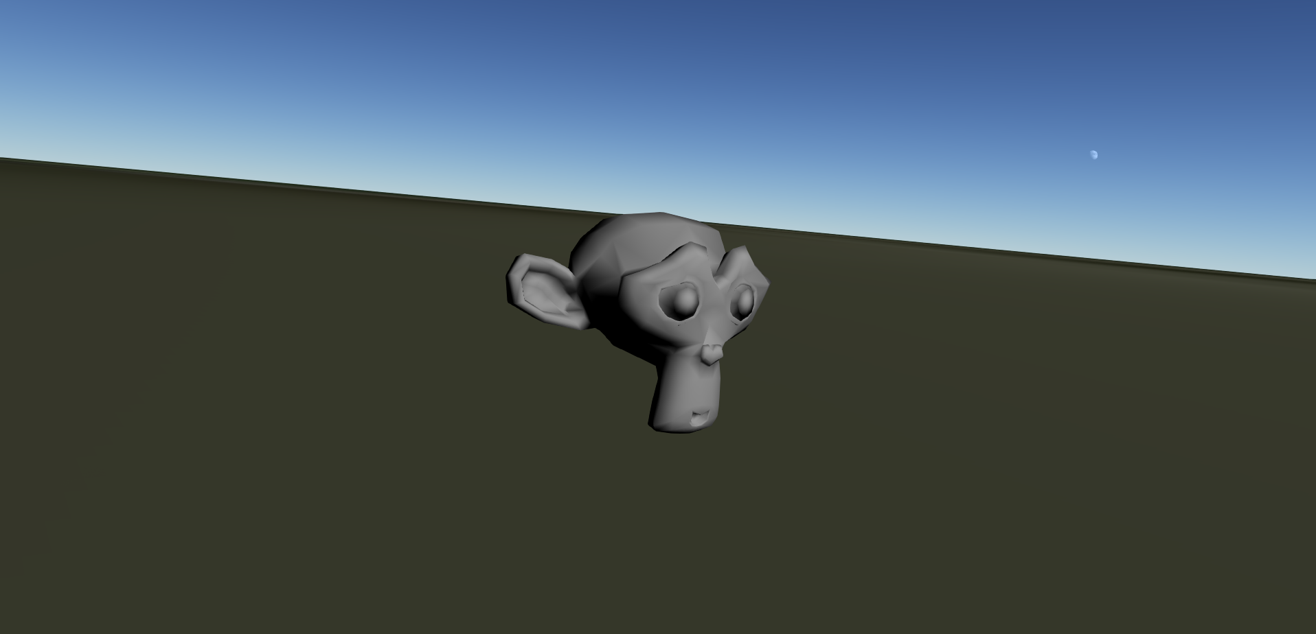
In this article we will cover the basics of placing model on the surface of a planet or moon. In this case we will be adding a model of a monkey head to the surface of the Earth. The example module can be downloaded from here ModelOnSurfaceExample.zip. This module adds a model that looks like the screenshot below:

We talk about the the mod and configuration files in this article, and hopefully provide a framework for modifying the files discussed below so that you can place your on models on the surface of the planet or moon of your choice. While it is not discussed here, if you want to change the appearance of the module in the profile editor, then you should change the module.definition and description.html files.
ModelOnSurfaceExample.mod

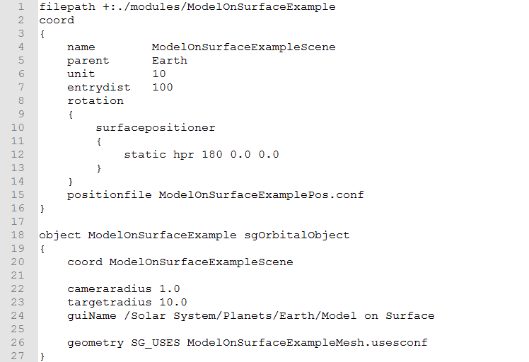
This is the mod file for the module. Its name should be the same as the name of the directory that contains the custom module. The first line adds the custom module directory to the list of directories Uniview searches through, and the lets you use file paths relative to the custom module directory.
The next block, lines 2 through 16, add a new scene that we will use to place our model. We give our scene a unique name on line 4, and a parent scene on line 5. Since we are placing our model on the surface of the Earth, the parent of our model's scene is the Earth scene. If we wanted to place the model on another planet or moon then we would change the parent scene to be the scene of that planet or moon. Line 6 sets the units of the scene in meters, so a distance of 1 in our new scene is a distance of 10 m. Line 7 sets the entry distance, which is the size of the scene. In this case, the model's scene is 100 scene units in radius. The rotation block, lines 8 through 14, set the rotation of the model relative to the surface of the Earth or other object. This is done by specifying the desired heading, pitch, and roll in degrees on line 12. Line 15 specifies a configuration file for the model's scene. This file specifies the location on the model's scene on the surface. We will talk about the contents of the position file below.
The final code block in the mod file actually creates the model object. Line 18 specifies both the name of the object (ModelOnSurfaceExample) and the type of object (sgOrbitalObject). Line 20 specifies the coordinate system that the object is defined in. In this case we want it to be the scene that we just defined above. Lines 22 and 23 specify the camera and target radii in scene units. The camera radius is the closest the camera is allowed to the origin of the object, and the target distance is how far the camera is from the origin object after a jump to or a fly to. Line 24 sets how the object appears in the Object Tree. These are specified from the top down where the levels are separated by "/". This means that our object will show up on the tree as "Model on Surface" under "Earth", which is under "Planets", etc. Line 26 sets the USES configuration file for the object, which is where we can specify the model and other properties.
ModelOnSurfaceExamplePos.conf

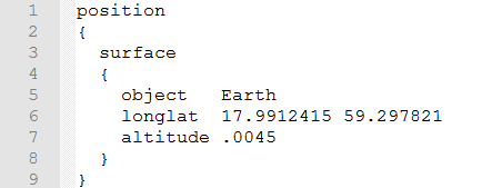
This files is the configuration file for the scene that we defined in the mod file above. The first few lines specify that this is a position file on the surface of an object. On line 5 we specify that we want this scene to be on the Earth's surface as opposed to the surface of a different planet or moon. If we wanted to put our model on the surface of a different planet or moor we would need to change this line to include the appropriate planet or moon. Line 6 specifies the longitude and latitude of the scene's origin. This is specified in degrees with East and North being positive and West and South being negative. Finally, line 7 specifies the altitude of the origin of the scene. This is specified in the planet's scene units, which for the Earth is 10 km, so the origin of this scene is 45 meters above the surface of the Earth.
ModelOnSurfaceExampleMesh.usesconf

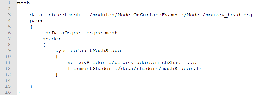
This is a simple example of a USES
configuration file, as is specified by the first line. The third line
specifies the model that we are going to use. It loads the monkey
head model in and gives it the local name of "objectmesh". Lines
4 through 15 specify the first, and in this case only, pass, or
shader execution. The sixth line says that this pass should be
executed on the data the was loaded as "objectmesh", which is our
monkey head model. Line 9 specifies the type of shader.
For models this should be kept as “defaultMeshShader”. Lines 11
and 12 specify the shaders that are used to render out the specified
mesh. In this case, we just specify the default mesh shaders for
clarity, however you could specify custom shaders here as well.
Customer support service by UserEcho

